Here is a quick introduction to using the traffic light module. Hopefully it will provide you with the confidence include the beginnings of traffic control in your project.
This example will demonstrate the use of an Arduino UNO in controlling the module. Once connected and the program loaded, lights will perform a pedestrian crossing sequence and provide feedback to the serial monitor.
Components
Wiring
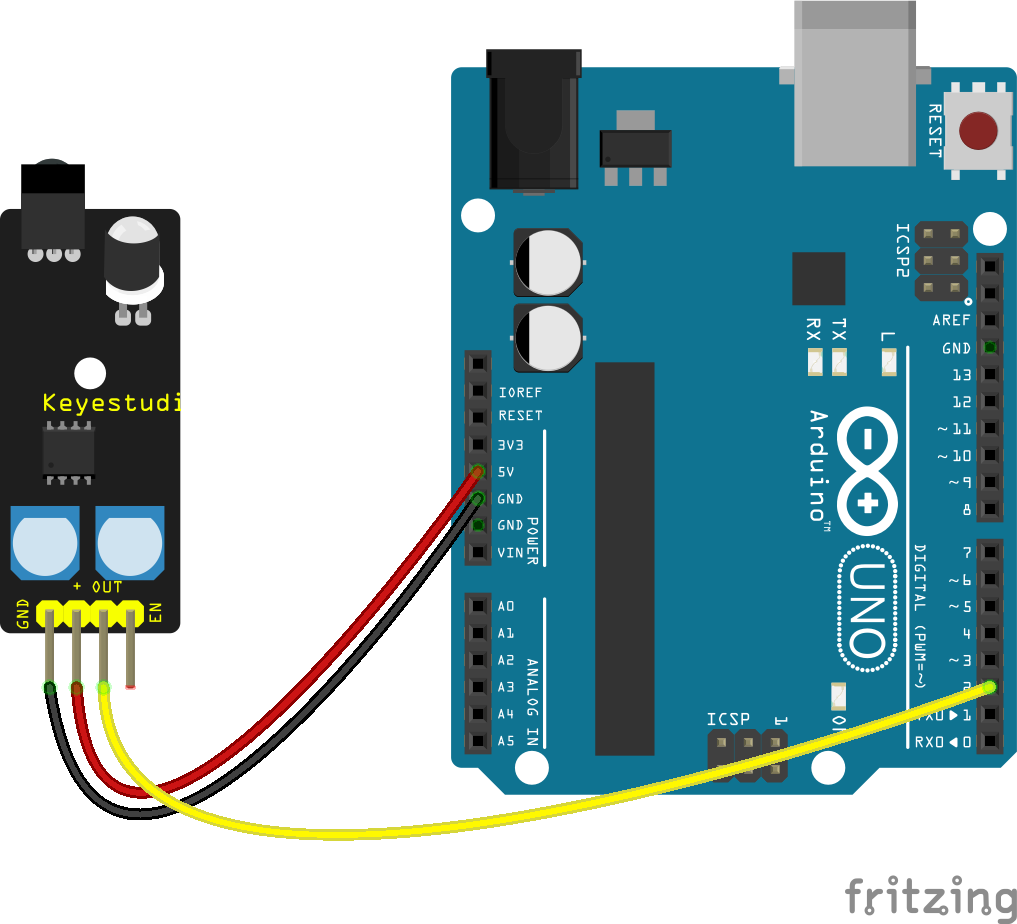
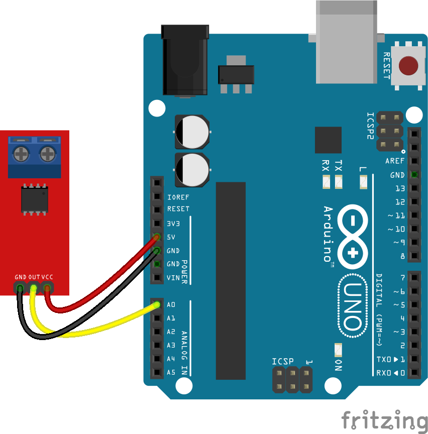
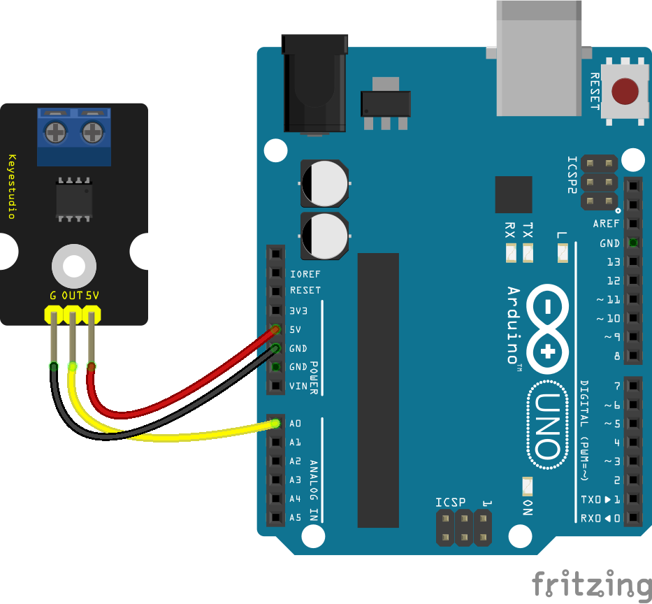
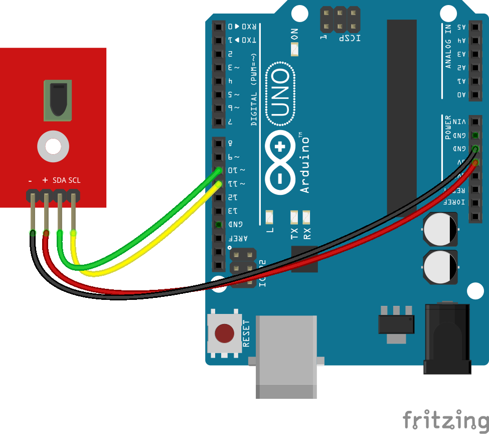
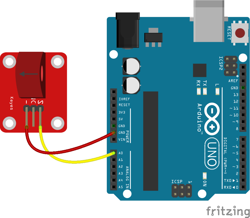
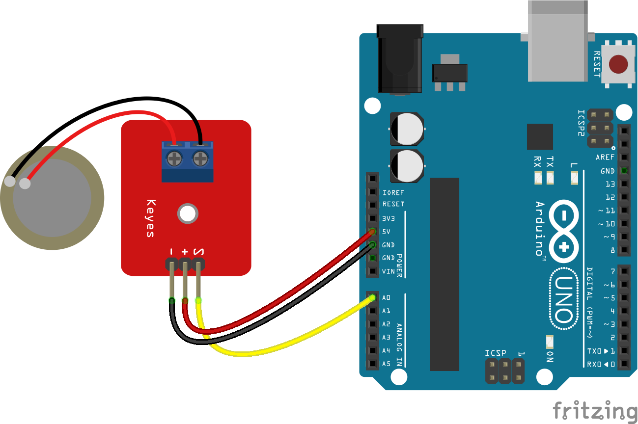
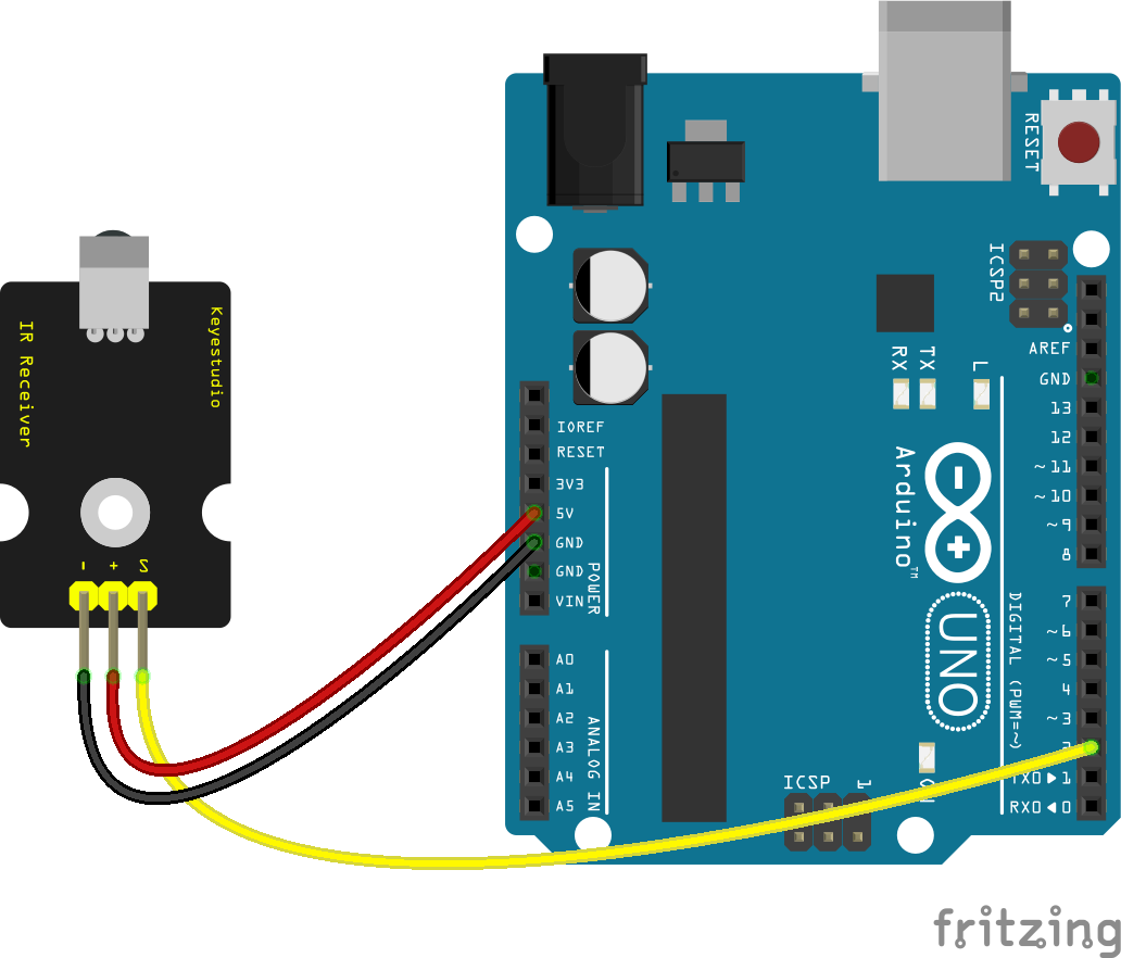
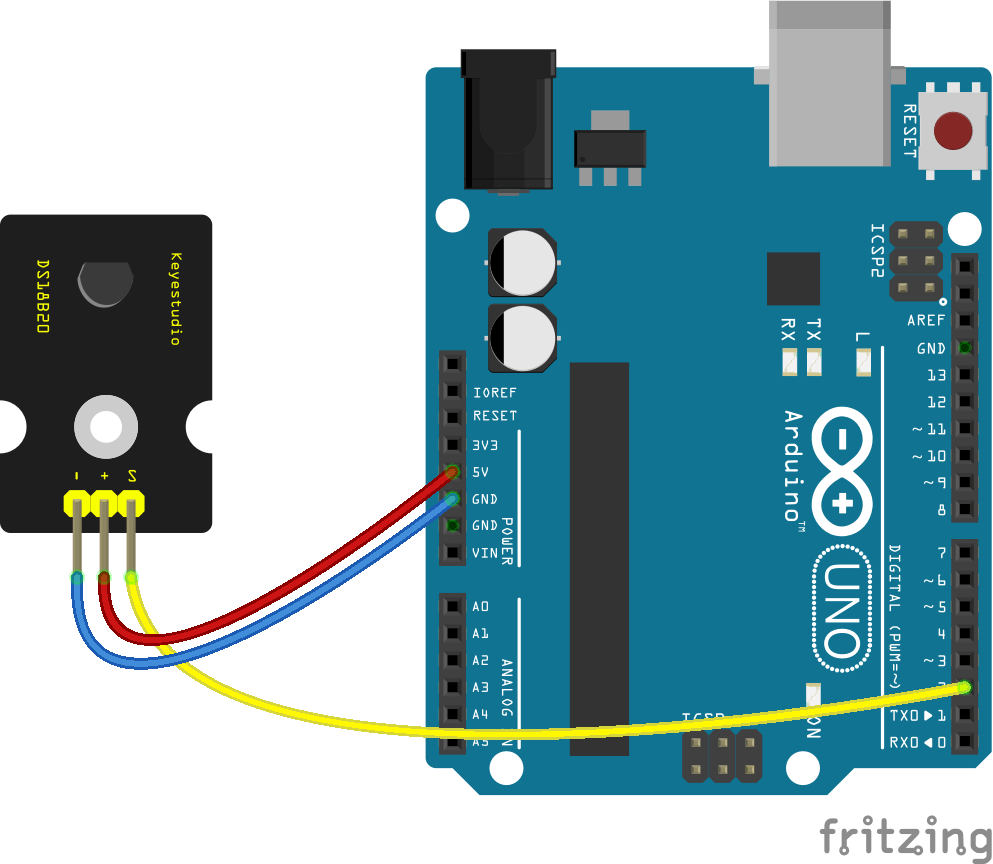
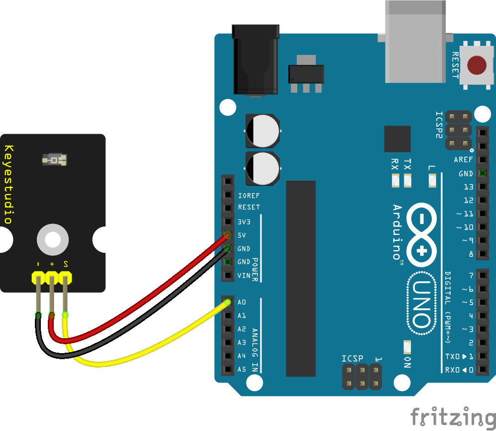
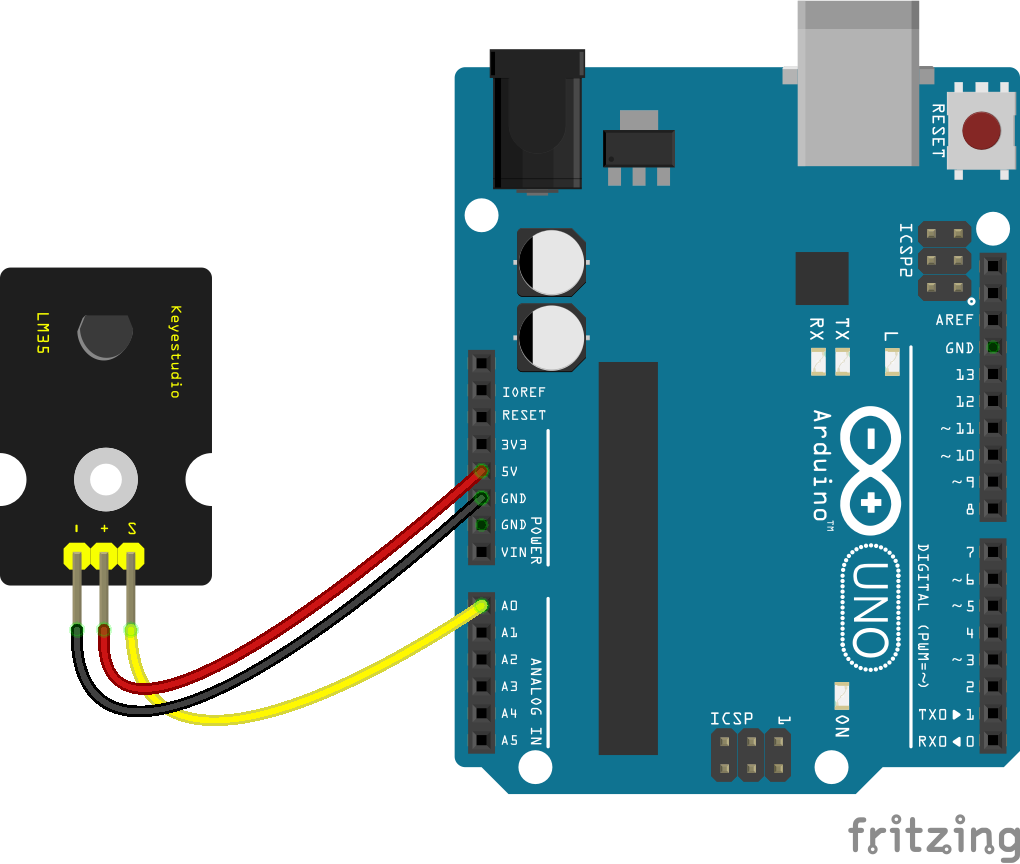
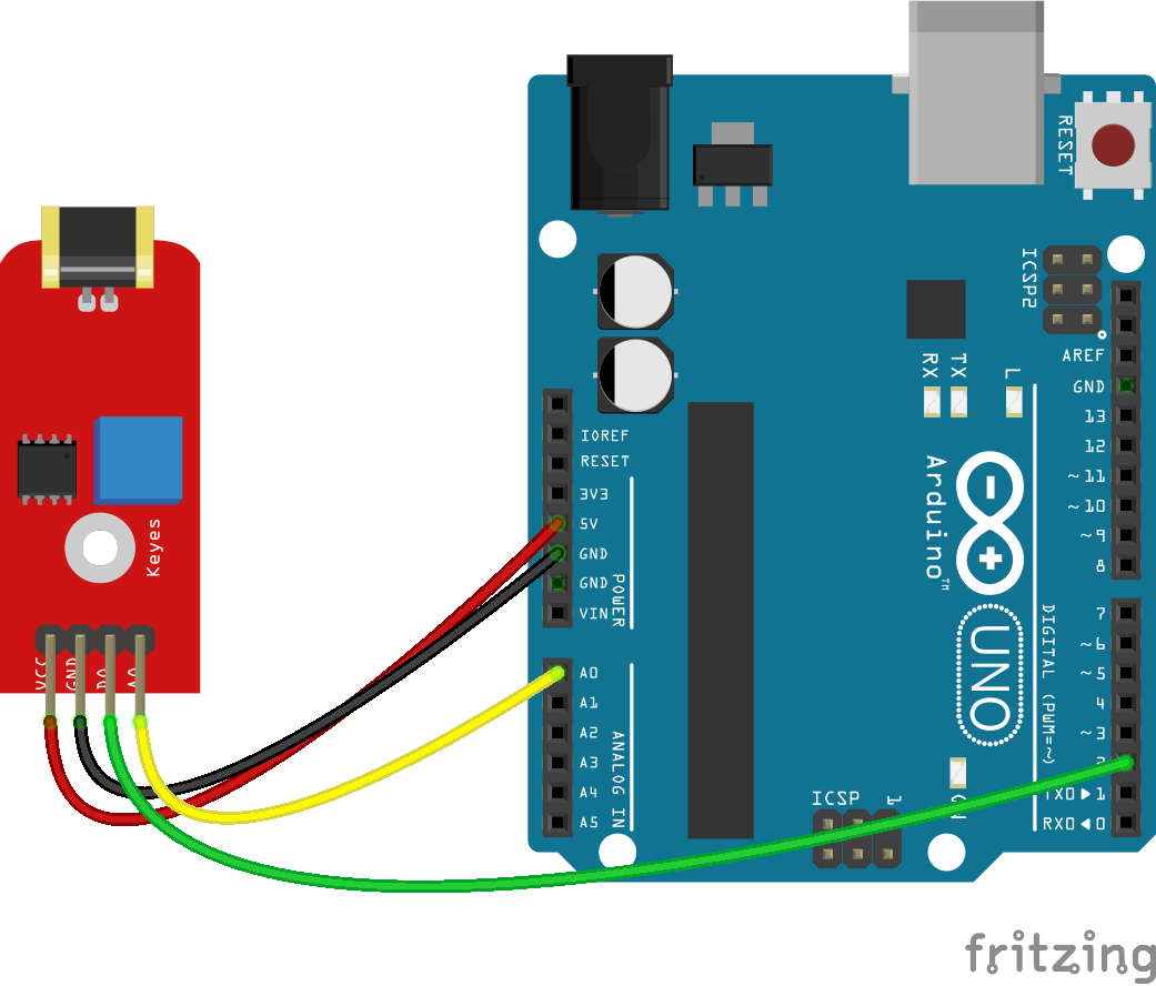
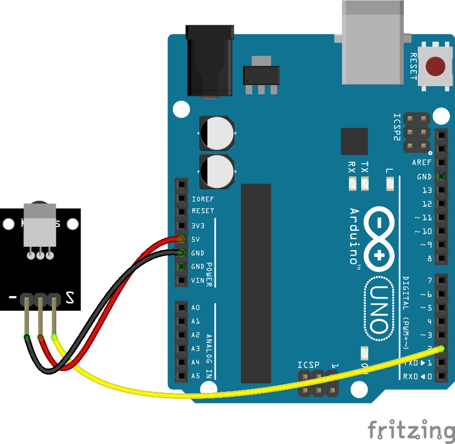
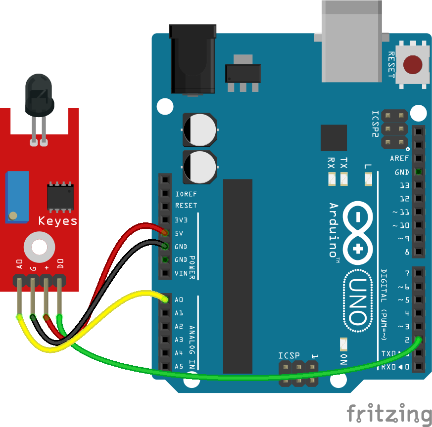
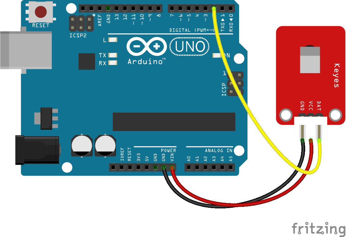
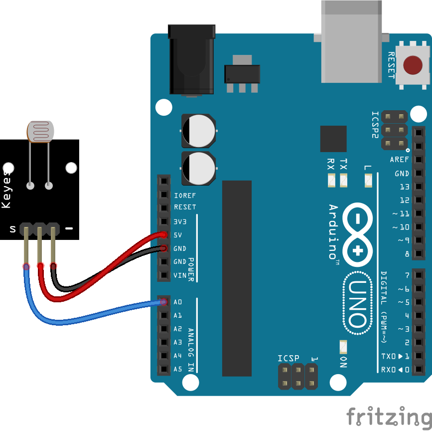
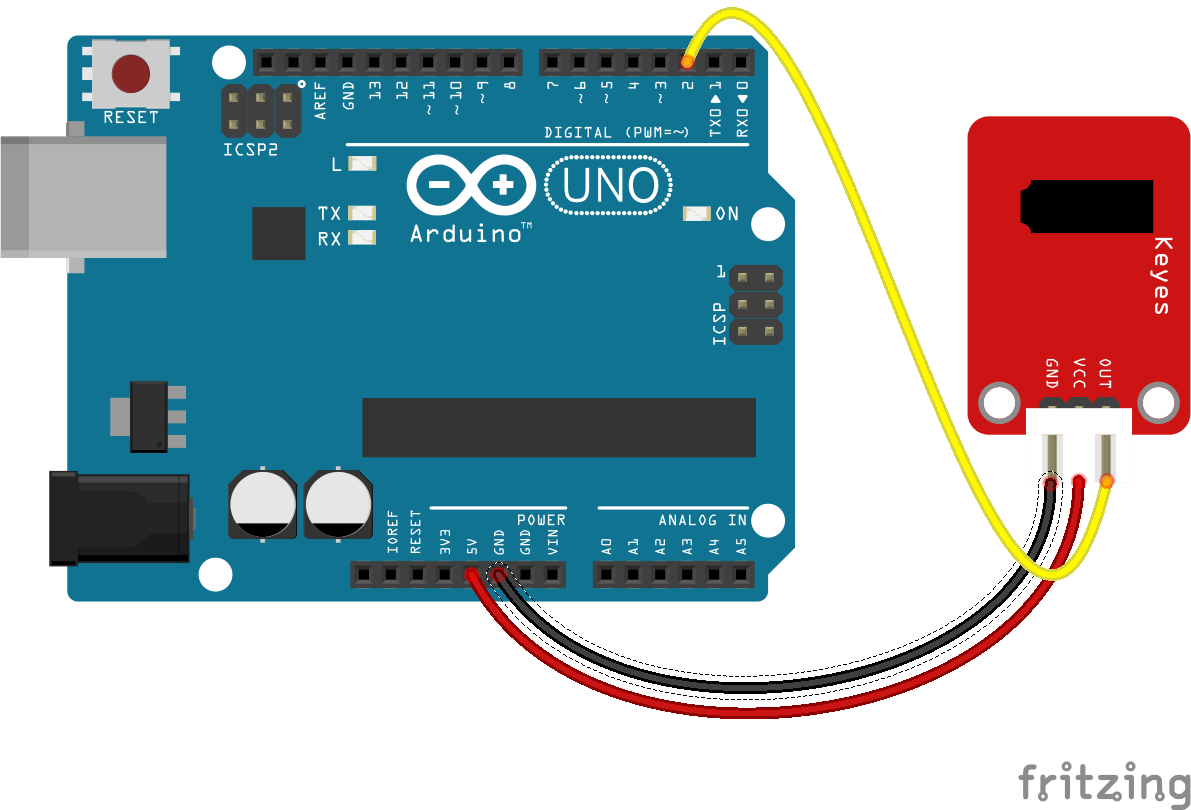
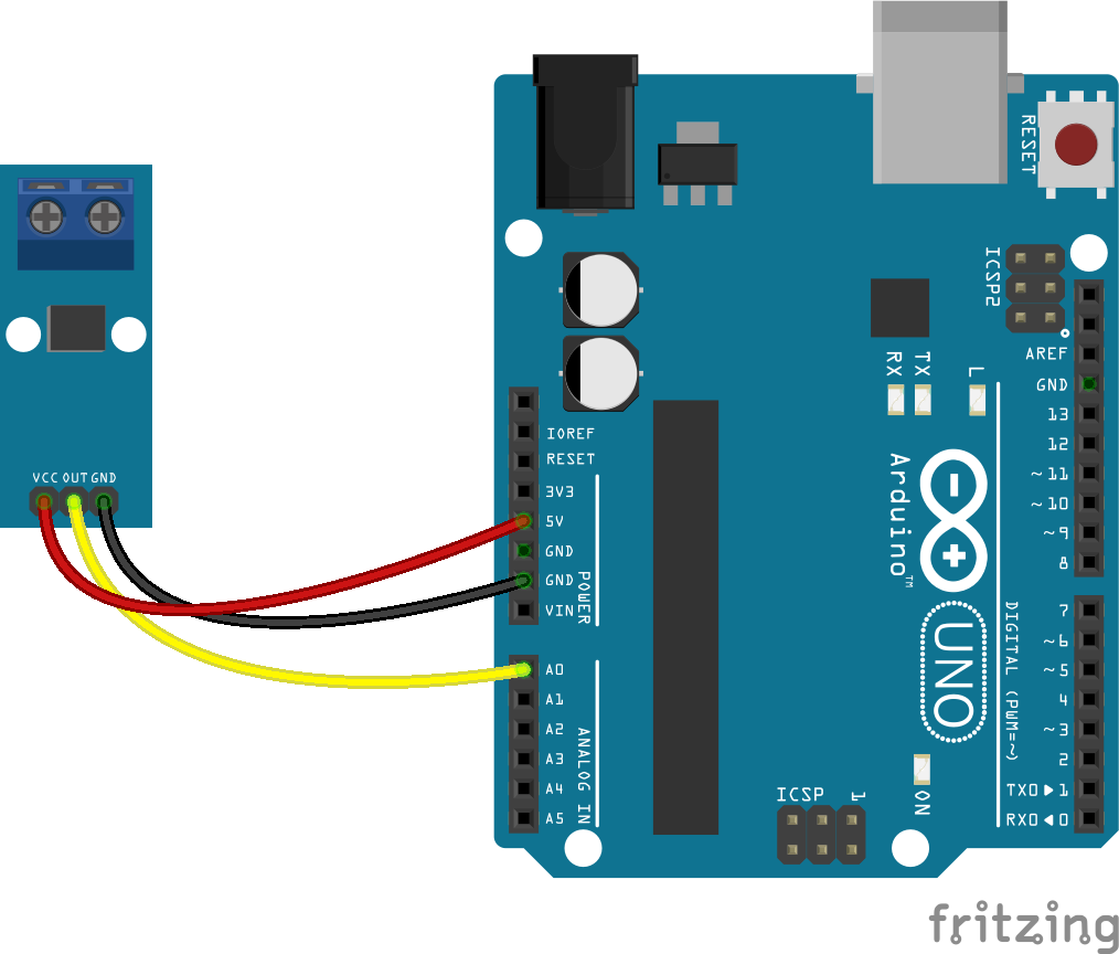
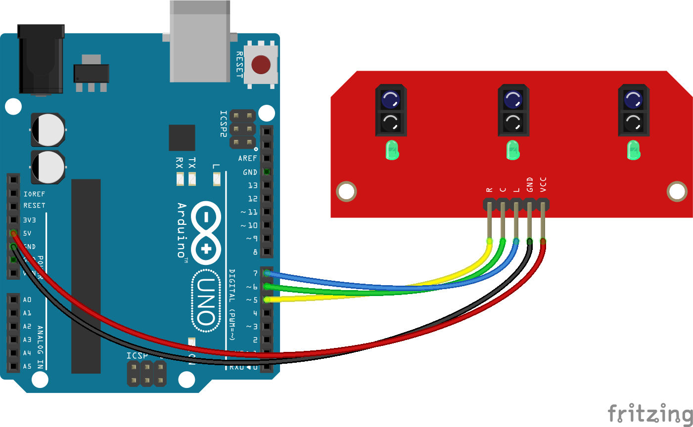
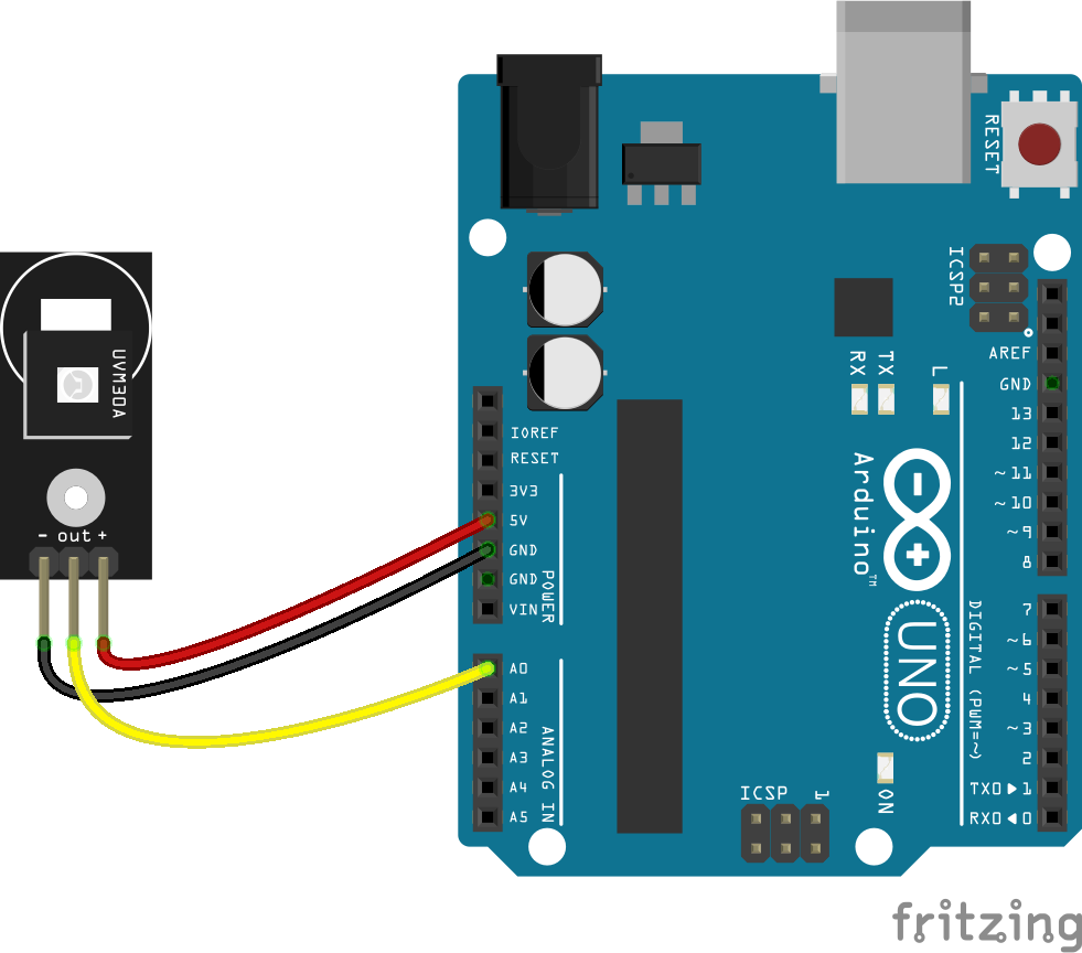
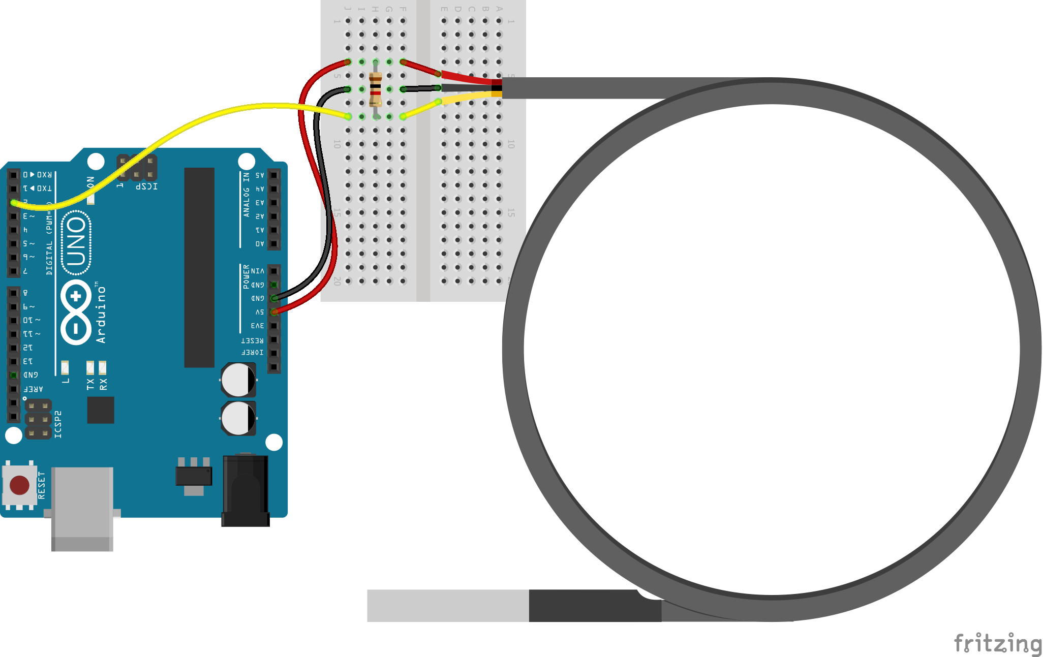
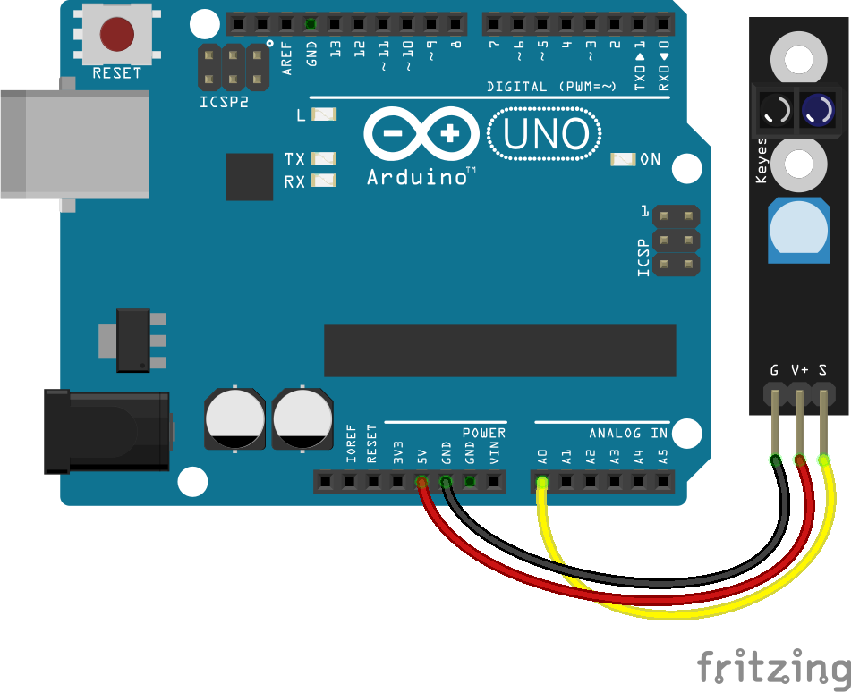
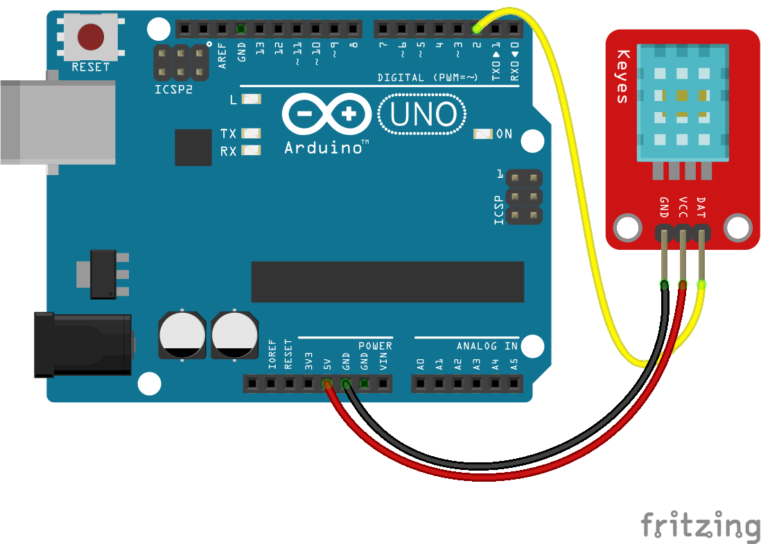
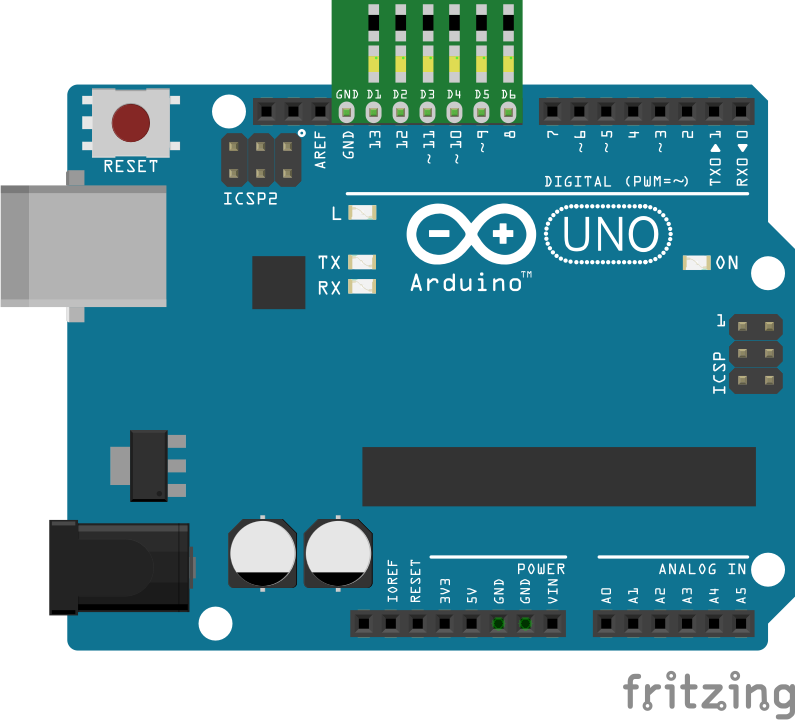
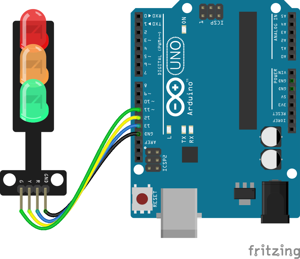
Wire the two boards together as can be seen in the image below, taking care to match the pin numbers.
Coding
The code consists of the definitions, a setup and a single loop. Initially the pin numbers and delay lengths are defined. Following this the setup defines the pins as outputs, sets them to a starting value and then launches the serial monitor. The loop contains the control program that will run continuously after the setup. The loop monitors the serial input for the letter 'P'. Once it has been entered into the monitor, the sequence begins. First the green light is extinguished and the amber light lit. A loop cycles it through a number of times as defined by the earlier declared delay variable, each cycle passes through a pause. On completion the amber turns to red and it pauses once more in the same fashion. Following which the flashing amber state is reached. The flashing is controlled by doubling the amber delay, halving the pause and toggling the amber pin on each loop through. Once this has been completed the sequence finalises, the green is lit and the initial state restored.
Load the code below into the Arduino IDE and upload it to your board.
/*
  A simple program designed to setup and demonstrate the 3 Traffic Light LED module - BBAA100043
  The program simulates a simple pedestrian crossing.
  modified 21 June 2019
  by Sebastian Karam - Flux Workshop
*/
int redLEDpin = 13; // pin number for the red LED
int amberLEDpin = 12; // pin number for the amber LED
int greenLEDpin = 11; // pin number for the green LED
int amberDelay = 5; // pause in seconds to maintain the amber light
int redDelay = 10; // pause in seconds to maintain the red light
void setup() {
  pinMode(redLEDpin, OUTPUT); // set the R signal pin as an output
  pinMode(amberLEDpin, OUTPUT); // set the Y signal pin as an output
  pinMode(greenLEDpin, OUTPUT); // set the G signal pin as an output
  digitalWrite(redLEDpin,LOW); // set the red LED to off by default
  digitalWrite(amberLEDpin,LOW); // set the amber LED to off by default
  digitalWrite(greenLEDpin,HIGH); // set the green LED to on by default
  Serial.begin(9600); // launch the serial monitor
  Serial.println("Flux Workshop Traffic Light Example");
  Serial.println("Enter P to Cross");
}
void loop() {
  // send data only when you receive data:
  if (Serial.available() > 0) { // check if data is available on the serial input
    char input = Serial.read(); // store the serial data in a variable
    if (input == 'P'){ // check if the incoming data is the letter 'P'
      Serial.println("--- BUTTON HAS BEEN PRESSED ---");
      Serial.println("--- GOING TO AMBER ---");
      for (int count = 0; count <= amberDelay; count++){ // Loop through the amber sequence
        digitalWrite(amberLEDpin,HIGH); // set the amber LED to on
        digitalWrite(greenLEDpin,LOW); // set the green LED to off
        delay(1000);
      }
      Serial.println("--- GOING TO RED ---");
      for (int count = 0; count <= redDelay; count++){ // Loop through the amber sequence
        digitalWrite(amberLEDpin,LOW); // set the amber LED to off
        digitalWrite(redLEDpin,HIGH); // set the red LED to on
        delay(1000);
      }
      Serial.println("--- GOING TO FLASHING AMBER ---");
      for (int count = 0; count <= amberDelay*2; count++){ // Loop through the flashing amber sequence
        digitalWrite(amberLEDpin,!digitalRead(amberLEDpin)); // toggle the amber LED
        digitalWrite(redLEDpin,LOW); // set the red LED to off
        delay(500); // this is a shortened delay for it to flash faster
      }
      Serial.println("--- GOING TO BACK TO GREEN ---");
      digitalWrite(amberLEDpin,LOW); // set the amber LED to off
      digitalWrite(greenLEDpin,HIGH); // set the green LED to on
      delay(1000);
      Serial.println("Enter P to Cross"); // resend the instruction
    }
  }
}
Running
With the board loaded with the program and all the connections made the serial monitor will begin and await the input of the letter 'P'. The sequence will then begin. The output should be as seen below. Please note the camera has a hard time dealing with bright LEDs.
What to try next?
- Trigger a beeper as the sequence run like a pedestrian crossing.
- Set the sequence into a container function and build up a full traffic junction.
]]>