Let's Workshop: 760-1100nm Keyes IR Detector Module
Posted by Sebastian Karam on
Here is a quick introduction to using the Keyes IR Detector module. Hopefully it will provide you with the confidence to intergrate IR light sensing into your project.
This example will demonstrate the use of an Arduino UNO in monitoring an analog pin over the range of light levels that an IR detector responds to.
Components
- 1pcs Arduino UNO or Compatible - LCAA100005
- 1pcs Keyes IR Detector Module - BDAA100013
- 4pcs Male to Female Jumper Cables - GBAA100002
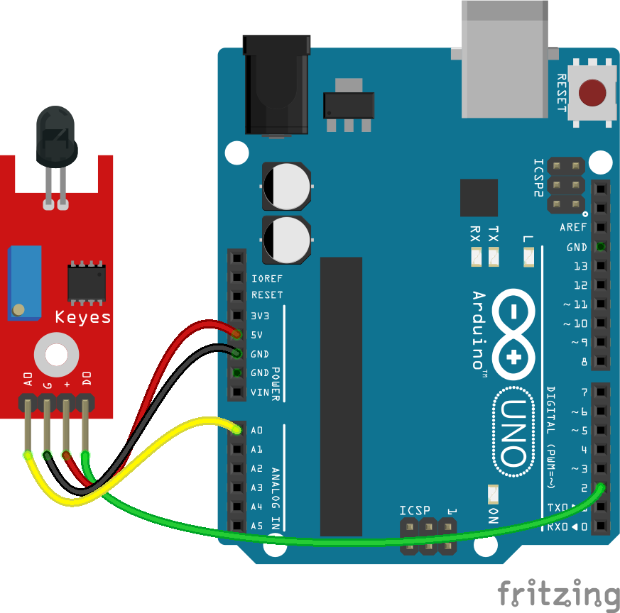
Wiring
Wire the one of the two boards to the Arduino as can be seen in the images below, taking care to match the pin numbers.
Coding
The code consists of a definition, setup and loop. First the A0 and D0 pins is assigned followed by a varaiable each to store the values read. This allows easier use later in your program. A setup informs the system that the pins are inputs and then lauches the serial connection. Next we enter the loop, where the value on the pin is read and stored in the variables declared earlier. Following that we send it to the serial monitor so that the value can be read on the screen.
Load the code below into the Arduino IDE and upload it to your board.
/*
  A simple program designed to setup and demonstrate the Keyes IR Detector Module - BDAA100013.

  The program monitors connected analog and digital pin and outputs the value to the
  serial monitor.

  modified 19th September 2019
  by Sebastian Karam - Flux Workshop
*/
int analogpin = 0; // define analog OUT signal pin
int analog; // define variable to store value read from pin
int digitalpin = 2; // define digital OUT signal pin
int digital; // define variable to store value read from pin

void setup() {
  pinMode(analogpin, INPUT); // set the OUT signal pin as an input
  pinMode(digitalpin, INPUT); // set the OUT signal pin as an input
  Serial.begin(9600); // launch the serial monitor
  Serial.println("Flux Workshop Example");
}

void loop() {
  analog = analogRead(analogpin);  // read the voltage level on the A0
  digital = digitalRead(digitalpin);  // read the voltage level on the D2
  Serial.println((String)"Light level: Analog " + analog + " Digital " + digital ); // send the result to the serial monitor
  delay(200); // pause for a moment before repeating
}
Running
With the board loaded with the program and all the connections made the serial monitor will produce an output like the one seen below. In this case the sensor is in a moderately lit room, resulting in a background value on the analog output. Taking a common TV remote, the emitter is held up to the detector and a button pressed. You can then see a spike in the output.
What to try next?
- Use the output to recieve a signal or message from an emitter, while avoiding it being visible by the human eye.
- Use the sensor as to monitor a daylight times.
Share this post
- 0 comment
- Tags: BDAA100013, Detector, Invisible, Invisisisibubble, IR, Keyes, Remote Control, Sensor, TV