Let's Workshop: Keyes ML8511 Ultraviolet Sensor Module
Posted by Sebastian Karam on
Here is a quick introduction to using the Keyes ML8511 ultraviolet light sensor module. Hopefully it will provide you with the confidence to integrate UV light sensing into your project, maybe even helping you get a tan.
This example will demonstrate the use of an Arduino UNO in monitoring an analog pin over changing light levels that the sensor responds to.
Components
- 1pcs Arduino UNO or Compatible - LCAA100005
- 1pcs Keyes ML8511 Ultraviolet light Sensor Module - BDAA100024
- 3pcs Male to Female Jumper Cables - GBAA100002
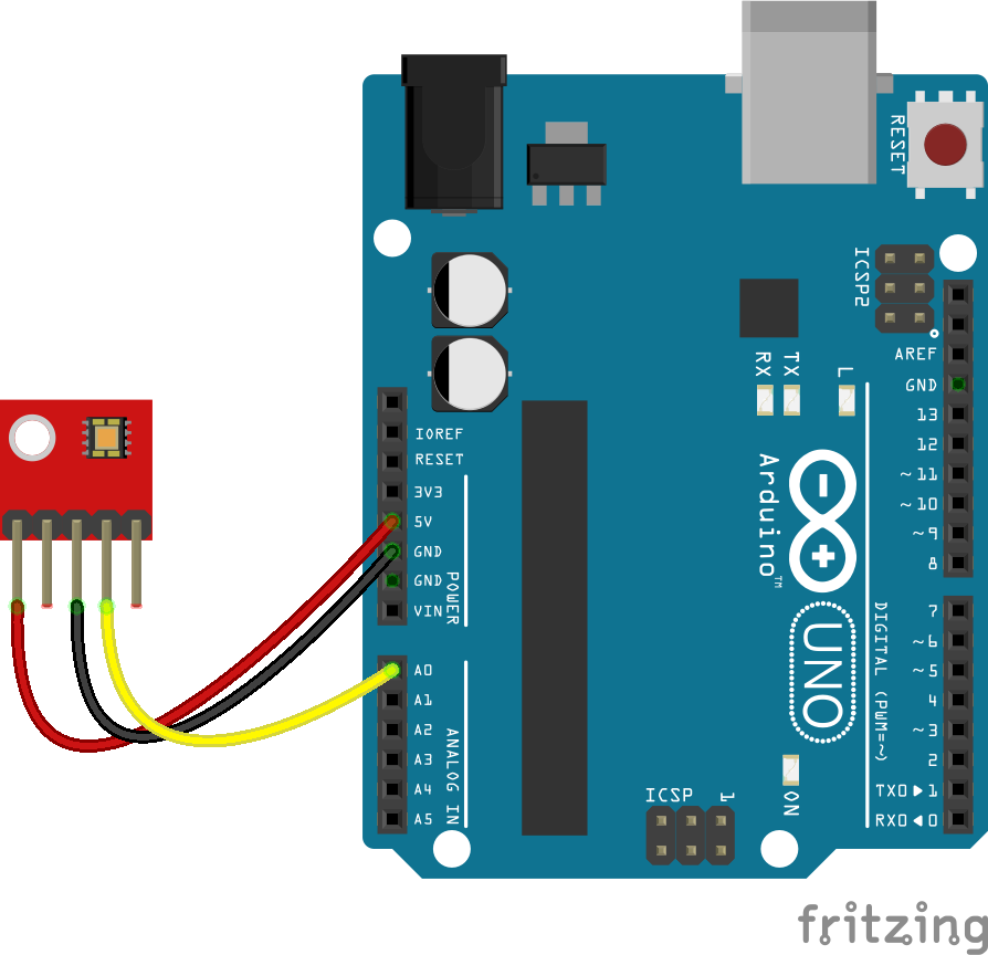
Wiring
Wire the one of the two boards to the Arduino as can be seen in the images below, taking care to match the pin numbers.
Coding
The code consists of a definition, setup and loop. First the A0 pin is assigned followed by a varaiable to store the value read. This allows easier use later in your program. A setup informs the system that the pin is an input is an input and then lauches the serial connection. Next we enter the loop, where the value on the pin is read and stored in the variable declared earlier. Following that we send it to the serial monitor so that the value can be read on the screen.
Load the code below into the Arduino IDE and upload it to your board.
/*
  A simple program designed to setup and demonstrate the Keyes ML8511 ultraviolet sensor module - BDAA100024

  The program monitors a connected analog pin and outputs the value to the
  serial monitor.

  modified 20th November 2019
  by Sebastian Karam - Flux Workshop
*/
int analogApin = 0; // define OUT signal pin
int analogA; // define variable to store value read from pin

void setup() {
  pinMode(analogApin, INPUT); // set the OUT signal pin as an input
  Serial.begin(9600); // launch the serial monitor
  Serial.println("Flux Workshop Example");
}

void loop() {
  analogA = analogRead(analogApin);  // read the voltage level on the A0
  Serial.println((String)"UV level: " + analogA); // send the result to the serial monitor
  delay(200); // pause for a moment before repeating
}
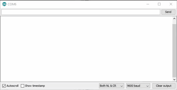
Running
With the board loaded with the program and all the connections made the serial monitor will produce an output like the one seen below. In this case the sensor is in daylight before it is covered. Note the values are low even when detecting, thanks to the lovely British weather we had no sun for the test. When in full sun/under a UV lamp the results should read around 240.
What to try next?
- Use the output to monitor sunrise and sunset.
- Factor in the readings into a weather station, to help guide sunscreen and shade use.
Share this post
- 93 comments
- Tags: Arduino, Cloudy with a chance of no UV, Keyes, ML8511, Module, Sensor, Ultraviolet, UNO, UV
xmFTUfJzwYyVHIO
QTVCheRKLxNcgiE
XzRkLsdWtn
wozeZkLQg
hPSIEJVRv