Let's Workshop: Keyes TA12-200 Current Sensor Module
Posted by Sebastian Karam on
Here is a quick introduction to using the Keyes TA12-200 based current sensor module. Hopefully it will provide you with the confidence to start monitoring exactly how much power those tea drinkers are actually using.
This example will demonstrate the use of an Arduino UNO in monitoring an analog pin state as the current sensor monitors an AC live wire.
Components
- 1pcs Arduino UNO or Compatible - LCAA100005
- 1pcs Keyes Current Sensor Module - BDAA100023
- 2pcs Male to Male Jumper Cables - GBAA100001
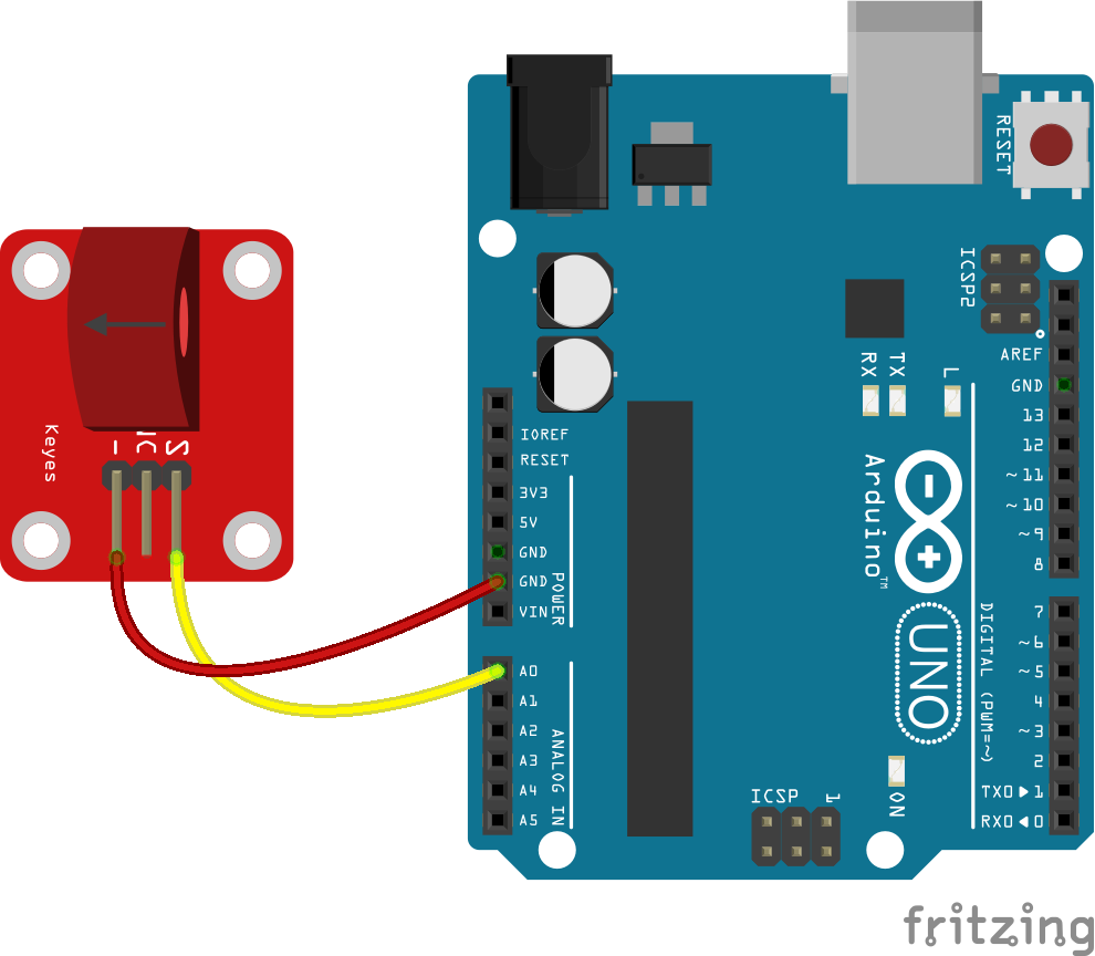
Wiring
Wire the two boards to the Arduino as can be seen in the images below, taking care to match the pin numbers and names.
Coding
The code consists of a definition, setup and loop. First the A0 pin is assigned followed by a variable to store the value read. This allows easier use later in your program. A setup informs the system that the pin is an input is an input and then launches the serial connection. Next we enter the loop, where the value on the pin is read and stored in the variable declared earlier. Following that we send it to the serial monitor so that the value can be read on the screen.
Load the code below into the Arduino IDE and upload it to your board.
/*
  A simple program designed to setup and demonstrate the Keyes Current Sensor Module - BDAA100023.

  The program monitors a connected analog pin and outputs the value to the
  serial monitor.

  modified 6th November 2019
  by Sebastian Karam - Flux Workshop
*/
int analogApin = 0; // define OUT signal pin
int analogA; // define variable to store value read from pin

void setup() {
  pinMode(analogApin, INPUT); // set the OUT signal pin as an input
  Serial.begin(9600); // launch the serial monitor
  Serial.println("Flux Workshop Example");
}

void loop() {
  analogA = analogRead(analogApin);  // read the voltage level on the A0
  Serial.println((String)"Current level: " + analogA); // send the result to the serial monitor
  delay(200); // pause for a moment before repeating
}
Running
With the board loaded with the program and all the connections made the serial monitor will produce an output like the one seen below. In this instance, the live wire of a kettle is passed through the sensor, then I began turning it on and off. You will notice outputs reaches its maximum when it is turned on.
What to try next?
- Use the output over a long time to monitor power consumption.
- Set a trigger to alert you when a particular current level is reached, potentially protecting vulnerable devices.
Hello, nice post. I’m currently working with the sensor for my bachelor’s thesis and would like to display it in Fritzing. Where did you get the Fritzing file from? I need this sensor in Fritzing but can’t find it anywhere
The circuit puts an AC voltage on the Arduino ADC, which can only accept DC voltages. You need to bias the AC voltage up.
vqJWKDuTj
hmYGHXDbwpUZ
OLEPJgldpqC