Let's Workshop: Keyestudio ACS712 5A Current Sensor Module
Posted by Sebastian Karam on
Here is a quick introduction to using the Keyestudio ACS712 5A sensor module. Hopefully it will provide you with the confidence to integrate current sensing into your project.
This example will demonstrate the use of an Arduino UNO in monitoring an analog pin voltage level as a current is applied to the terminals over the range that the sensor responds to.
Components
- 1pcs Arduino UNO or Compatible - LCAA100005
- 1pcs Keyestudio ACS712ELC-05B 5A Current Sensor Module - BDAA100027
- 3pcs Male to Female Jumper Cables - GBAA100002
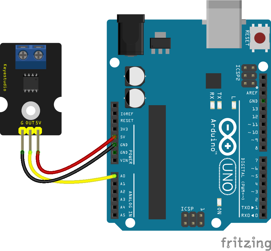
Wiring
Wire the two boards to the Arduino as can be seen in the images below, taking care to match the pin numbers.
Coding
The code consists of a definition, setup and loop. First the A0 pin is assigned followed by a variable to store the value read. This allows easier use later in your program. A setup informs the system that the pin is an input is an input and then launches the serial connection. Next we enter the loop, where the value on the pin is read and stored in the variable declared earlier. As the analog pins interpret values over a 1024 part range, we do some simple scaling for our amp range of -5 to 5A. Following that we send the value to the serial monitor so that the value can be read on the screen.
Load the code below into the Arduino IDE and upload it to your board.
/*
  A simple program designed to setup and demonstrate the Keyestudio ACS712 5A sensor module - BDAA100027

  The program monitors a connected analog pin, interprets a voltage level and outputs the value to the
  serial monitor.

  modified 5th December 2019
  by Sebastian Karam - Flux Workshop
*/
int analogApin = 0; // define OUT signal pin
int analogA; // define variable to store value read from pin

void setup() {
  pinMode(analogApin, INPUT); // set the OUT signal pin as an input
  Serial.begin(9600); // launch the serial monitor
  Serial.println("Flux Workshop Example");
}

void loop() {
  analogA = analogRead(analogApin);  // read the voltage level on the A0
  Serial.println((String)"Current: " + (((analogA-512)*10)/1024) + "A"); // send the result to the serial monitor
  delay(500); // pause for a moment before repeating
}
Running
With the board loaded with the program and all the connections made the serial monitor will produce an output like the one seen below. In this case the sensor is in line with a 2A device. When powered, the sensor picks it out at 2A. The polarity is then switched and it goes to -2A.
What to try next?
- Use the output along with a voltmeter to monitor power usage over a period.
- Set a trigger to alert you when a particular value of current is detected.
Share this post
- 102 comments
- Tags: 5A, ACS712, Amp, Arduino, Big Fat Wires, Current, Keyestudio, Module, Sensor, UNO
WiUBJjGfMYKPkdw
gsRBowbJCnHVXLc
zJIwCSYUXpDFVy
HVNvdgCGxYbcSX
cvONipLbtghq