Let's Workshop: Keyestudio Obstacle Detector Module
Posted by Sebastian Karam on
Here is a quick introduction to using the Keyestudio obstacle detector module. Hopefully it will provide you with the confidence to object light reflection into your project. Providing an ideal launch point for a robot, vacuum cleaner, lawnmower or other.
This example will demonstrate the use of an Arduino UNO in monitoring a digital pin when an object is placed in front of the detector.
Components
- 1pcs Arduino UNO or Compatible - LCAA100005
- 1pcs Keyestudio Obstacle Detector Module - BDAA100029
- 3pcs Male to Female Jumper Cables - GBAA100002
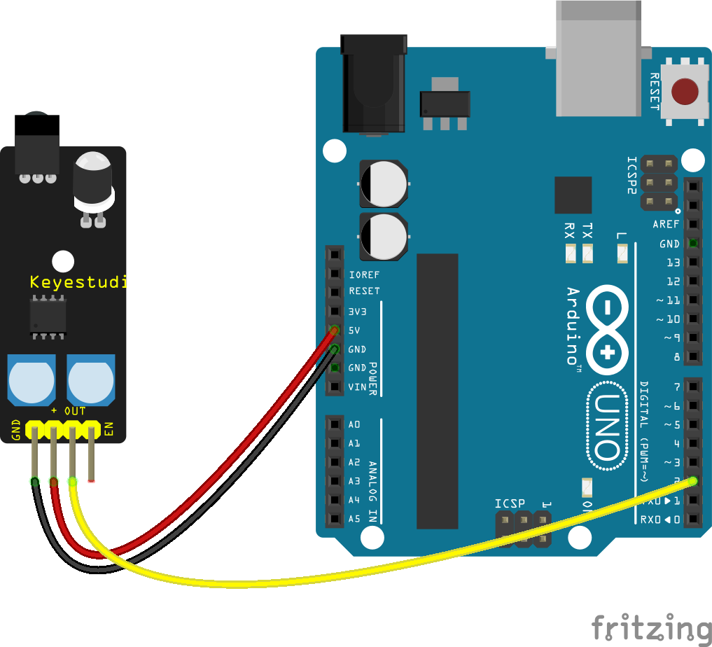
Wiring
Wire the one of the two boards to the Arduino as can be seen in the images below, taking care to match the pin numbers.
Coding
The code consists of a definition, setup and loop. First the D2 pin is assigned followed by a variable to store the values read. This allows easier use later in your program. A setup informs the system that the pins are inputs and then launches the serial connection. Next we enter the loop, where the value on the pin is read and stored in the variable declared earlier. Following that we send it to the serial monitor so that the value can be read on the screen.
Load the code below into the Arduino IDE and upload it to your board.
/*
  A simple program designed to setup and demonstrate the Keyestudio obstacle detection Module - BDAA100029.

  The program monitors connected digital pin and outputs the value to the
  serial monitor.

  modified 19th December 2019
  by Sebastian Karam - Flux Workshop
*/
int digitalpin = 2; // define digital OUT signal pin
int digital; // define variable to store value read from pin

void setup() {
  pinMode(digitalpin, INPUT); // set the OUT signal pin as an input
  Serial.begin(9600); // launch the serial monitor
  Serial.println("Flux Workshop Example");
}

void loop() {
  digital = digitalRead(digitalpin);  // read the voltage level on the D2
  Serial.println((String)"Detection Level: " + digital ); // send the result to the serial monitor
  delay(200); // pause for a moment before repeating
}
Running
With the board loaded with the program and all the connections made the serial monitor will produce an output like the one seen below. Taking my hand and placing it front of the detector and emitter. You can then see a grounding in the output.
What to try next?
- Use the onboard potentiometers to adjust the sensitivity of the trigger.
- Investigate the response of the sensor to different materials.
Share this post
- 134 comments
- Tags: BDAA100029, Detector, IR, Keyes, Keyestudio, Lawnmower, Module, Obstacle, Roooooooooomba
MkcPZGdKoLmR
qpSngPfxQRwDOE
nzlrQOytTjJvNxY
wcARYfPJ
hVdJaqLfWX