Let's Workshop: Keyes 8 RGB LED Line
Posted by Sebastian Karam on
Here is a quick introduction to using the Keyes 8 RGB LED line module. Hopefully it will provide you with the confidence to push on to more advanced visual displays.
This example will demonstrate the use of an Arduino UNO in the control of the 8 RGB LED module. Once connected and the program loaded, the LEDs will cycle through the 3 individual colours of each LED in sequence, looping endlessly.
Components
- 1pcs Arduino UNO or Compatible - LCAA100005
- 1pcs 8 RGB LED Line Module Keyes - BBAA100005
- 12pcs Male to Female Jumper Cables - GBAA100002
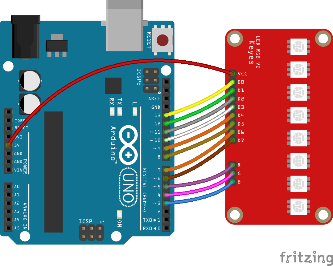
Wiring
Wire the two boards together as can be seen in the image below, taking care to match the pin numbers.
Coding
The code consists of the a setup and loop. The setup defines the pins to be used in the control of the module. The loop contains the control program that will run continuously after the setup. It is made up of two loops, one nested inside the other. The outer loop controls the colour pin selected and the inner one selects a particular LED in the array.
The loop sets both the colour and LED select pin to LOW, triggering the LED. It then waits for a 100ms before setting the LED select back to HIGH and moving to the next LED.
Load the code below into the Arduino IDE and upload it to your board.
/*
  A simple program designed to setup and demonstrate the 8 RGB LED Line Module - BBAA100005

  The program selects a colour and lights each LED in order.
  Once looped, it will change to the next colour and repeat.

  modified 13 December 2018
  by Sebastian Karam - Flux Workshop
*/

// these constants won't change:
const int ledCount = 8;    // the number of LEDs in the display
const int colourCount = 3;    // the number of colours in the display
int ledPins[] = { 6, 7, 8, 9, 10, 11, 12, 13};   // an array of pin numbers to which LEDs are attached
int colourPins[] = { 3, 4, 5};   // an array of pin numbers to which LEDs are attached

void setup() {
  // loop over the LED pin array and set them all to output:
  for (int thisLed = 0; thisLed < ledCount; thisLed++) {
    pinMode(ledPins[thisLed], OUTPUT);
    digitalWrite(ledPins[thisLed],HIGH);
  }
  // loop over the colour pin array and set them all to output:
  for (int thisColour = 0; thisColour < colourCount; thisColour++) {
    pinMode(colourPins[thisColour], OUTPUT);
    digitalWrite(colourPins[thisColour],HIGH);
  }
}

void loop() { // the loop function runs over and over again forever
  // colour loop
  for (int thisColour = 0; thisColour < colourCount; thisColour++) {
    digitalWrite(colourPins[thisColour],LOW); // sets the colour
    // LED loop
    for (int thisLed = 0; thisLed < ledCount; thisLed++) {
       digitalWrite(ledPins[thisLed],LOW); // illuminates the LED
       delay(100);
       digitalWrite(ledPins[thisLed],HIGH); // extinguishes the LED
    }
    digitalWrite(colourPins[thisColour],HIGH);
  }
}
Running
With the board loaded with the program and all the connections made the module should start to scroll through the colours as seen below.
What to try next?
- Change the digital colour select over to analog, outputting values between 0-5V.
- Setting combinations of colour pins LOW at the same time