Let's Workshop: 3 Line Sensor Module
Posted by Sebastian Karam on
Here is a quick introduction to using the 3 line line sensor module. Hopefully it will provide you with the confidence to object light reflection into your project. Providing an ideal launch point for a line following Arduino robot.
This example will demonstrate the use of an Arduino UNO in monitoring digital pins that output readings from 3 IR detectors. Each responding as it moves from a white reflective surface to a black absorbent one.
Components
- 1pcs Arduino UNO or Compatible - LCAA100005
- 1pcs 3 Ch Infrared White/Black Line Detection Module - BDAA100003
- 5pcs Male to Female Jumper Cables - GBAA100002
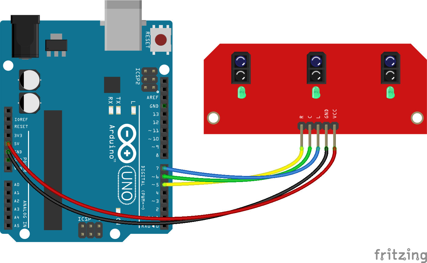
Wiring
Wire the one of the two boards to the Arduino as can be seen in the images below, taking care to match the pin numbers.
Coding
The code consists of a definition, setup and loop. First the 3 digital pins is assigned followed by individual variables to store the value read. This allows easier use later in your program. A setup informs the system that the pins are inputs and then launches the serial connection. Next we enter the loop, where the values on the pins are read and stored in the variables declared earlier. Following that we send it to the serial monitor so that the value can be read on the screen. As a final addition, a series of 'if' statements read the output (which is combined into a single string above). These then output a relevant message to reflect a robots reaction to the line position.
Load the code below into the Arduino IDE and upload it to your board.
/*
  A simple program designed to setup and demonstrate the a 3 line following module.

  The program monitors connected digital pins and outputs the value to the
  serial monitor. The output is then run through a simple set of if statements to demonstrate
  a line robots reactions.

  modified 19th July 2019
  by Sebastian Karam - Flux Workshop
*/
int digitalLpin = 7; // define L signal pin
int digitalCpin = 6; // define C signal pin
int digitalRpin = 5; // define R signal pin
int digitalL; // define variable to store value read from pin
int digitalC; // define variable to store value read from pin
int digitalR; // define variable to store value read from pin

void setup() {
  pinMode(digitalLpin, INPUT); // set the L signal pin as an input
  pinMode(digitalCpin, INPUT); // set the C signal pin as an input
  pinMode(digitalRpin, INPUT); // set the R signal pin as an input
  Serial.begin(9600); // launch the serial monitor
  Serial.println("Flux Workshop Example");
}

void loop() {
  digitalL = digitalRead(digitalLpin);  // read the voltage level on the D7
  digitalC = digitalRead(digitalCpin);  // read the voltage level on the D6
  digitalR = digitalRead(digitalRpin);  // read the voltage level on the D5
  Serial.println((String)"L: " + digitalL + " C: " + digitalC + " R: " + digitalR); // send the result to the serial monitor
  String reading = String(digitalL) + String(digitalC) + String(digitalR); // builds the result into a single string
  if(reading == "011"){
    Serial.println("Turn right, turn right!"); // the line is being detected on the left
  }
  if(reading == "101"){
   Serial.println("We have the line!");  // the line is being detected in the center
  }
  if(reading == "110"){
    Serial.println("Turn left, turn left!");  // the line is being detected on the right
  }
  delay(500); // pause for a moment before repeating
}
Running
With the board loaded with the program and all the connections made the serial monitor will produce an output like the one seen below. In this case the sensor is moved from looking at white paper across a black line and back. The response changes as each sensor passes across the line, triggering the 'if' statement response. You will notice when one of the states are not met, no message other then the output values are returned. These will need to be considered unknown responses to a robot and may call back to its last known trigger.
What to try next?
- Integrate motor control into the 'IF' statements to steer a robot.
- The sensor is based on reflected IR light, as such many surfaces reflect, which offers possibilities in proximity detection combined with position.
Share this post
- 2 comments
- Tags: Arduino, BDAA100003, Following, IR, Line, Robot, UNO
Could I have the fritzing file of the 3-Channel-Sensor-Module please?
can i get fritzing?