Let's Workshop: 5V 1 Channel Relay Module
Posted by Sebastian Karam on
Here is a quick introduction to using a 5V 1 channel relay module. Hopefully it will provide you with the confidence to integrate a relay into your project and begin controlling large mains powered devices.
This example will demonstrate the use of an Arduino UNO in toggling a relay trigger. Once connected and the program loaded, it will toggle the state of the relay and then monitor the state of the outputs.
Components
- 1pcs Arduino UNO or Compatible - LCAA100005
- 1pcs 5V 1 Channel Relay Module - BHAA100036
- 3pcs Male to Male Jumper Cables - GBAA100001
- 3pcs Male to Female Jumper Cables - GBAA100002
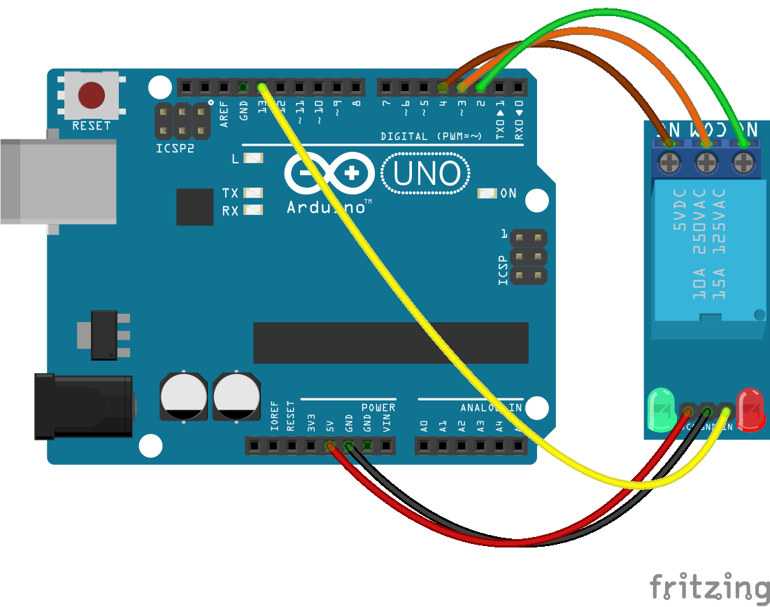
Wiring
Wire the two boards together as can be seen in the image below, taking care to match the pin numbers.
Coding
The code consists of definitions, setup and loop. First the 4 pins used a defined, this is followed by their initialisation taking care to set the 'COM' and 'IN' pins as outputs. The 'COM' pin state is then pulled 'LOW' and the pull-up resistors are enabled for the 'NC' and 'NO'. The use of the pull-up resistors prevents the pin values from floating indeterminately, pulling them 'HIGH' when not connected to ground. The setup finally initialises the serial connection. The loop then toggles the state of the 'IN' pin by using the 'NOT' (!) operator. Pausing for a second before the pins states are read and relayed to the serial monitor. During the pause you will hear the sound of the mechanical switch within the relay toggling.
Load the code below into the Arduino IDE and upload it to your board.
/*
  A simple program designed to setup and demonstrate the a 5V 1 channel
  relay module - BHAA100036

  The program toggles a digital pin state to which toggles the relay. The output
  state is then measured and output to the serial monitor.

  modified 12 April 2019
  by Sebastian Karam - Flux Workshop
*/

const int NO = 2; // normally open screw terminal
const int com = 3; // common screw terminal
const int NC = 4; // normally closed screw terminal
const int IN = 13; // trigger pin (LOW to trigger)

void setup() {
  pinMode(NO, INPUT); // set the normally open pin as an input
  pinMode(com, OUTPUT); // set the common pin as an output
  pinMode(NC, INPUT); // set the normally closed pin as an input
  pinMode(IN, OUTPUT); // set the trigger pin as an output
  digitalWrite(com, LOW); // set the common pin to LOW
  digitalWrite(NO, HIGH); // use the Arduino's internal pull-up resistor on the NO pin
  digitalWrite(NC, HIGH); // use the Arduino's internal pull-up resistor on the NC pin
  Serial.begin(9600); // launch the serial monitor
  Serial.println("Flux Workshop Example");
}

void loop() {
  digitalWrite(IN, !digitalRead(IN)); // toggle the trigger pin state
  delay(1000); // pause to allow the mechanical process to complete
  Serial.println((String)"IN: " + digitalRead(IN) + " NO: " + digitalRead(NO) + " NC: " + digitalRead(NC));
  delay(2000); // pause before looping
}
Running
With the board loaded with the program and all the connections made, start the serial monitor. First you will hear the relay toggling, with a very audible 'click'. Watching the monitor you will see that the 'IN' state is changing between '0' and '1', with that the state of the 'NC' and 'NO' pins change. When 'IN' is '0' the relay is triggered; 'NO' connects to 'com', setting it to '0'. In combination, 'NC' is pulled up to 1 as it is not connected to 'com'. This the switches round as the relay toggles.
What to try next?
- Control a light bulb by running it power source through the relay.
- Use a sensor to provide the 'IN' trigger.
Share this post
- 2 comments
- Tags: 1 Channel, 5V, BHAA100036, Module, Relay
Muchas gracias. ?Como puedo iniciar sesion?
Hi, can you give me the schematic of the relay module 5v for fritzing?