Let's Workshop: LC Technology AT24C64 EEPROM Memory Module
Posted by Sebastian Karam on
Here is a quick introduction to using the LC Tech AT24C64 EEPROM memory module. This will provide you with an entry point to using a memory module that will save data and store it when power is removed.
This example will demonstrate the use of an Arduino UNO in selecting the module from the i2c bus and storing a string of characters at a defined memory location. Once stored, it will read back the message. This will use the AT24CX library created by Christan Paul to interface with the chipset and provide memory functions.
Components
- 1pcs Arduino UNO or Compatible - LCAA100005
- 1pcs LC Tech AT24C64 EEPROM Memory Module - BFAA100004
- 4pcs Male to Female Jumper Cables - GBAA100002
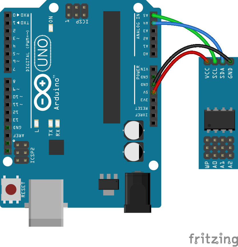
Wiring
Wire the two boards together as can be seen in the image below, taking care to match the pin numbers.
Coding
The code consists of an include, definitions, initialisation, setup and loop. First the Wire.h standard library and the AT24CX library is linked to the code. This is followed by the definition of the i2c address and pagesize which are then used to initialise a memory object. Launching the serial monitor provides a method to debug our output. In the loop we first define the address, message and message size that is required to write it to the memory module. With all the entered variables the message is written to the memory using the writeChars function. With the message stored, we now define the read variables before reading the message stored at the address. This is done with the readChars function the result of which is stored in the read_msg array and then printed to the serial monitor. A final while catch is put in to restrict the loop to a single run.
Load the code below into the Arduino IDE and upload it to your board.
/* A simple program designed to setup and demonstrate the AT24CX library and LC Tech AT24C64 Memory Module - BFAA100004 The program uses the AT24CX library to initialise the AT24C64 chipset and writes a message to it before reading it back. modified 28 March 2019 by Sebastian Karam - Flux Workshop The AT24CX library created by Christian Paul https://github.com/cyberp/AT24Cx */ #include// include the Wire library #include // include the AT24CX library // edit the i2c address you have set your eeprom headers to (usually 0 - 8) byte i2caddress = 0; // 0 is the default //Model Pagesize //AT24C32 32 //AT24C64 32 //AT24C128 64 //AT24C256 64 //AT24C512 128 // edit the pagesize based on the chipset you are using byte pagesize = 32; // initialise an eeprom object with our settings AT24CX mem(i2caddress, pagesize); void setup() { // serial init Serial.begin(9600); // initialise the serial connection } void loop() { int write_mem_address = 0; // define the location in the memory to begin writing char write_msg[] = "Flux Workshop"; // define a series of characters int write_msg_size = sizeof(write_msg); // calculate the size of the message mem.writeChars(write_mem_address, write_msg, write_msg_size); // store the message in the module int read_mem_address = 0; // define the location in the memory to begin reading char read_msg[20]; // define an array to store the read message int read_msg_size = sizeof(read_msg); // calculate the size of the read_msg array mem.readChars(read_mem_address , read_msg, read_msg_size); // read the characters beginning at the address Serial.print(read_msg); while (1==1) {} // set the loop to only run once }
Running
With the board loaded with the program and all the connections made the serial monitor will very simply display the message that we stored on the module.
What to try next?
- Store a variable that will be accessed after you restart the Arduino
- Store a large amount of data and map it for later access
- Use multiple EEPROM modules on different i2c addresses
Share this post
- 2 comments
- Tags: Arduino, BFAA100004, EEPROM, LC Technology, Memory, UNO
The pins being used are SDA/SCL pins which are part of the I2C communication system. You can then instead connect them to any of the other I2C positions on the UNO board. For instance the two pins on the bottom left of the board on the image (pin 27: SDA and pin 28: SCL).
Hello. Is it possible to replace the pins A4 and A5 with others? For example, on A0 and A1? If possible, where in the program do I need to change this? Thanks.