Let's Workshop: LC Tech Rotary Encoder
Posted by Sebastian Karam on
Here is a quick introduction to using the LC Technology rotary encoder module. Hopefully it will provide you with the confidence to intergrate rotary control into your projects.
This example will demonstrate the use of an Arduino UNO in the recieving and basic processing of signals from a rotary encoder. Once connected and the program loaded, the UNO will monitor the encoder pins and increment or decrement a counter relative to the rotation of the control.
Components
- 1pcs Arduino UNO or Compatible - LCAA100005
- 1pcs Rotary Encoder Module LC Blue - BLCA100110
- 12pcs Male to Female Jumper Cables - GBAA100002
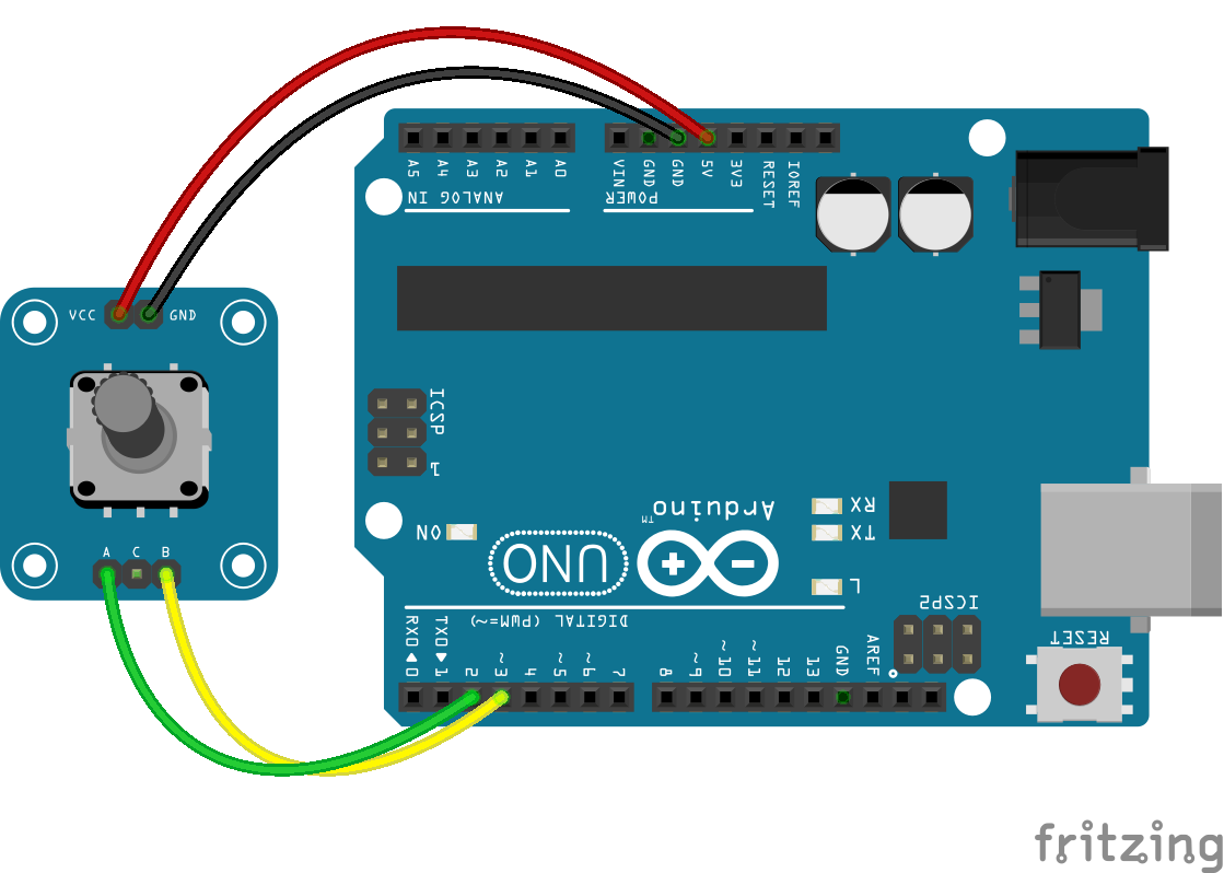
Wiring
Wire the two boards together as can be seen in the image below, taking care to match the pin numbers.
Coding
The code consists of the a setup and loop. The setup defines the pins to be used in the control of the module. The loop contains the control program that will run continuously after the setup. It is made up of two checks, one nested inside the other. The outer check triggers if there is a change in the state of the pins and the inner one determines the direction of the change before altering the counter accordingly.
On passing through both checks the counter is then passed on to the serial monitor system.
Load the code below into the Arduino IDE and upload it to your board.
/*
  A simple program designed to setup and demonstrate the Rotary Encoder Module LC Blue - BLCA100110

  The program monitors two inputs from the encoder.
  On a change, direction is obtained and relayed to the Arduino.
  A encoderCounter is then adjusted and sent to the serial monitor.

  modified 11 December 2018
  by Sebastian Karam - Flux Workshop
*/

// identify pins to used within the script
#define encoderA 2
#define encoderB 3

// declare global variables
int encoderCounter = 0; // holds encoderCounter that will be output to monitor
int encoderAState; // holds current state of the A pin
int startState; // holds start state of the A pin

void setup() {
  // set pins as inputs
  pinMode (encoderA,INPUT);
  pinMode (encoderB,INPUT);
  // open serial port at 9600 bps
  Serial.begin (9600);
  // determine the starting state of the encoderA
  int startState = digitalRead(encoderA);
}

void loop() { // the loop function runs over and over again forever
  encoderAState = digitalRead(encoderA); // read and store the current state of the A pin
  // Compare the previous and current states
  if (encoderAState != startState){
      if (digitalRead(encoderB) != encoderAState) {  // if the A and B pin states are different the encoder rotating clockwise
        encoderCounter++; // pins are different, increment the counter
      } else {
        encoderCounter--; // pins are the same, deincrement the counter
      }
   Serial.println(encoderCounter); // display the current counter in the monitor
 }
 startState = encoderAState; // updates the state of the A pin for the next loop
}
Running
With the board loaded with the program and all the connections made, start the serial monitor. An initial value for the counter may appear. Now twist the encoder knob, this will produce a series of outputs on the monitor. Reverse the direction and the counter will reverse. The output should be as seen below.

What to try next?
- Use the counter to control a servo's arm position.
- Investigate the use of interrupts for control
Share this post
- 9 comments
- Tags: BLCA100110, Encoder, Jan 2019, LC Technology, Rotary
] Ecueka eem.wjve.fluxworkshop.com.cwb.nh http://slkjfdf.net/
] Obehav tvl.sxok.fluxworkshop.com.umu.dp http://slkjfdf.net/
] Iberiho ezv.wact.fluxworkshop.com.qpo.bp http://slkjfdf.net/
] Olipoh bbo.dnch.fluxworkshop.com.vnp.np http://slkjfdf.net/